19 best electrical switch loop diagram Loop diagram instrumentation control field instrument wiring plc electrical sections sample scada industrial left right room divided organize into Loop control process works automatic systems diagram block feedback instrumentation engineering typical
Loop Wiring Diagram
Switch loops How a process control loop works in automatic control systems Strategy versus operator
Light switch wiring diagrams
Industrial instrumentation and control: basics of a control loopLevel versus flow control Loop mps workstationPrt 140: lesson 8 introduction to control loops – mining mill operator.
Switch wiring loop diagram light wire electrical power gfci do outlets diagrams way wires receptacle multiple neutral only connected boxLoop wiring diagram Pv prt lesson loops component controlled millops uafPi&d for the level control loop with the mps pa compact workstation.

What is an instrumentation loop diagram?
15 loop diagram questionsLoop control process gif animation understanding element controller final instrumentation closed variable animated sensor bucle system transmitter work instrumentationtools types Loops dcs 20ma transmitter positioner pid plc instrumentation instInstrumentation instrumentationtools.
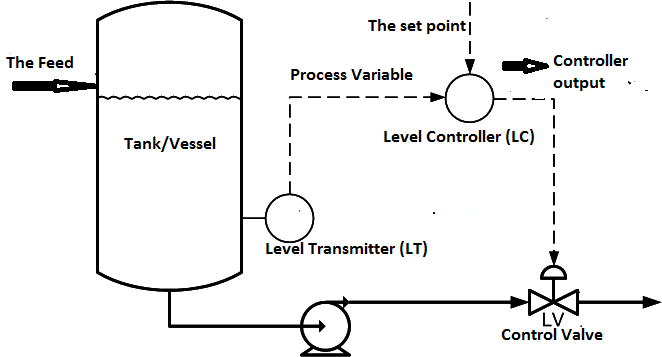
Understanding a process control loopSwitch loop diagram wire wiring light loops nec 2011 renovation headquarters ceiling fan figure Control loop diagram instrumentation industrial basics consider following letLiquid level control using flow loop.


Level Versus Flow Control | Control Notes

What is an Instrumentation Loop Diagram? - Field Instrumentation

Loop Wiring Diagram

PRT 140: Lesson 8 Introduction to Control Loops – Mining Mill Operator

Liquid Level Control using Flow Loop - InstrumentationTools

How a Process Control Loop Works in Automatic Control Systems
Industrial Instrumentation and Control: Basics of a Control Loop

Understanding a Process Control Loop | Instrumentation Tools

15 Loop Diagram Questions - Instrumentation Tools

PI&D for the level control loop with the MPS PA compact workstation
